Logic
The knowledge you gain about logic from Discrete Math (CSE 16) and Computer Systems and Assembly Language (CSE 12) will be some of the most commonly used skills in your career because of how frequently we use conditional statements and try to simplify them in code.
Definitions
- Bit: a bit is a binary value that is a 0 or a 1. Just one, not both, and nothing in between.
- Binary: a number system used in computer science that has only the numbers 0 and 1.
- Boolean: only has the value of True or False. Just one, not both, and nothing in between.
- Proposition: a logical expression that can be evalutated to a True or False value.
Logic Gates
This is one of the most common concepts you will come across when doing any programming. So, you will eventually memorize these, if you have not seen them before just from how often you will need to use them. All of the following gates are boolean/binary operations, which means that the inputs and outputs can only be True (1) or False (0) and nothing else and nothing in between.
AND
The AND gate can take in any number of input greater than 1. The truth table for the AND gate and its appearance in digital logic design is shown below.
In short, the AND gate returns/outputs a True (1), only when all of its inputs are True (1). It returns/outputs a False (0) otherwise (i.e. when at least one input is False (0) ).
Example: You want to check if A AND B AND C AND D are all True (1).
Example: You are making a new social media and working on how to have a user create a new account. You need to check if the user entered a valid email AND they are over a certain age AND entered a secure password.
OR
The OR gate can take in any number of input greater than 1. The truth table for the OR gate and its appearance in digital logic design is shown below.
In short, the OR gate returns/outputs a True (1), when at least one of its inputs are True (1). The other inputs can be anything else - there just has to be at least one True (1) in the inputs. It returns/outputs False (0) when all of the inputs are False (0).
Example: You want to check if any one of A OR B OR C OR D are True (1).
Example: You are making a scheduler. You want to check if the timer for the current task at hand has run out OR if the current task has finished so you can move on to another task. (This is one algorithm that a CPU may use schedule tasks in your computer!)
NOT
The NOT gate (also called an inverter) can take in 1 input and invert it. The truth table for the NOT gate and its appearance in digital logic design is shown below.
In short, if the input is a True (1), then the output is a False (0). If the input is a False (0), then the output is a True (1).
Example: You want to invert the truth value of one variable A.
Example: You are making a game and want to check when the player in the game is alive or dead so you know to continue the game or display the “game over” message. You make a conditional statement to continue running the game while the player is NOT dead.
XOR
The XOR gate can take any number of input greater than 1. The truth table for the XOR gate and its appearance in digital logic design is shown below. XOR stands for “exclusive or”, so one or the other but not both. The use of a XOR gate is not as common as the previous gates, but it still comes up and good to know.
In short, the XOR gate returns/outputs a True (1), if only 1 of the inputs is True (1) and False (0) otherwise.
- Example: A server sends 4 bits to a client and calculates the XOR of the 4 bits and the result is 1 and appends this resulting bit to the 4 (now 5) bit message to the client. The client can XOR the first 4 bits and if the result of the XOR is not the same as what the 5th bit says, then the message has been corrupted in transmission. But this is not a complete check since the message can be corrupted in a way that the server and client XOR results still line up.
Opposite Gates
Each one of the gates above have one that is the opposite as what it is normally. The AND gate has its opposite called NAND gate. OR has NOR. NOT/NO has BUFFER/YES. XOR has XNOR. The truth tables and digital logic design for all of these gates are also below. Essentially, just take the outputs of the normal gate and invert them and that is the truth table for the corresponding opposite gate.
Truth Tables
Truth tables can be tedious to make if there are a lot of inputs, but it is one of the most effective ways to visualize a problem. Similar to how Venn Diagrams are useful to help understand some set theory problems, truth tables are an excellent way to check if two statements are equivalent or not or simply evaluate an expression to see its resulting truth value.
Here is the visual for all of the logic gates described above. Now let us see how to read it.
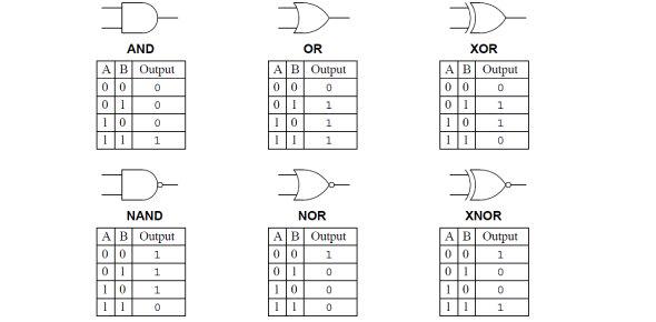
A visual guide to the common logic gates.
Diagram: Proprofs.com
(Click here to download the image if you want to save it for safe keeping.)
The $A$ and $B$ on the left columns are example inputs to the gate. Remember these can only be boolean/binary True (1)/False (0). They can the results of previously evaluated expression or a simple 1 or 0 as you see in the tables.
Notice that the inputs start at all 0 and then slowly work their way to all 1 at the bottom and that all of these rows make up every single possible combination of inputs that this gate have take. These are only 2 input gates, but you can come up with the tables for more inputs or Google them.
Now, look at the table one row at a time. Those two inputs get that gate operation applied to them and then the result is in the right side column.
Laws of Logic
This handout will be your best friend when working with logical expressions/equations that you need to evaluate or simplify. I will explain one rule on the handout so you know how to read and use it.
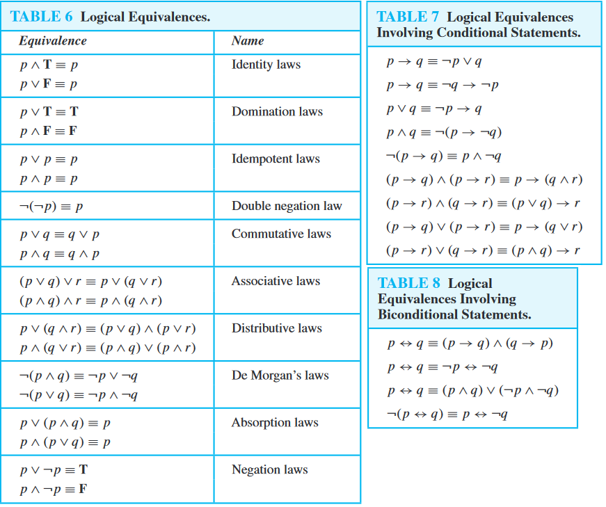
A reference chart for the laws of logic.
Diagram: math.stackexchange.com
(Click here to download the image if you want to save it for safe keeping.)
Notation in the Logic Laws
The T and F stand for True and False, respectively. The $p$, $q$, and $r$ used in the diagram are just variables that have boolean values. They can stand for a single variable in an equation or a piece of an expression (ex. $p$ can just be a variable in the equation as $p$ itself like how you can have $x$ in an expression in Calculus OR it can be representative for something bigger than a single variable like how you can have $x = (a + b/2)$ in Calculus). The $\equiv$ symbol means “logically equivalent” (i.e. equal to). The $\rightarrow$ symbol is called “the arrow of implication” read in an expression as “implies”. So $p \rightarrow q$ is read aloud as “$p$ implies $q$”.
Note: The first one in Table 7 is called “Definition of Implication” and the first one in Table 8 is called “Definition of Equivalence/Biconditional”.
Duals
Most of the logic laws have everything the same in their equations but the $\lor$ and $\land$ signs are flipped ($\lor$ becomes $\land$ and $\land$ becomes $\lor$). This operation of switching the ANDs and ORs is called “taking the dual”. In other words, one of these laws is the dual of the other (with the same name).
Note: The Double Negation, Defintion of Implication, and Definition of Equivalence do not have any duals.
Logic Law Handout Example
Let us take a look at the Commutative Laws. Notice how there are two Commutative Laws.
For the first Commutative Law, it says (in English): “the (truth) value of $p$ OR’ed with the (truth) value of $q$ is logically equivalent to the (truth) value of $q$ OR’ed with the (truth) value of $p$”. Notice how this is the same exact thing that you have seen before in previous math classes: $x + y = y + x$… same thing!